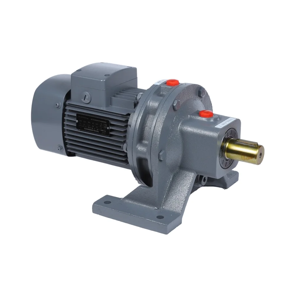
Motor speed reducers work like those gears on bicycles but for machines instead of people pedaling. When a small gear turns a bigger one, it slows things down but makes them stronger, just like when cyclists switch to lower gears for climbing hills. Take a look at those numbers: if there's a tiny 10 tooth gear connected to something massive with 100 teeth, we get what engineers call a 10 to 1 reduction ratio. What does all this mean? Well, factories need this kind of conversion because most motors spin really fast but don't have much power. The reducer takes that fast spinning and turns it into slow, powerful movement needed for cranes lifting tons of steel or conveyor belts moving heavy materials around manufacturing plants every day.
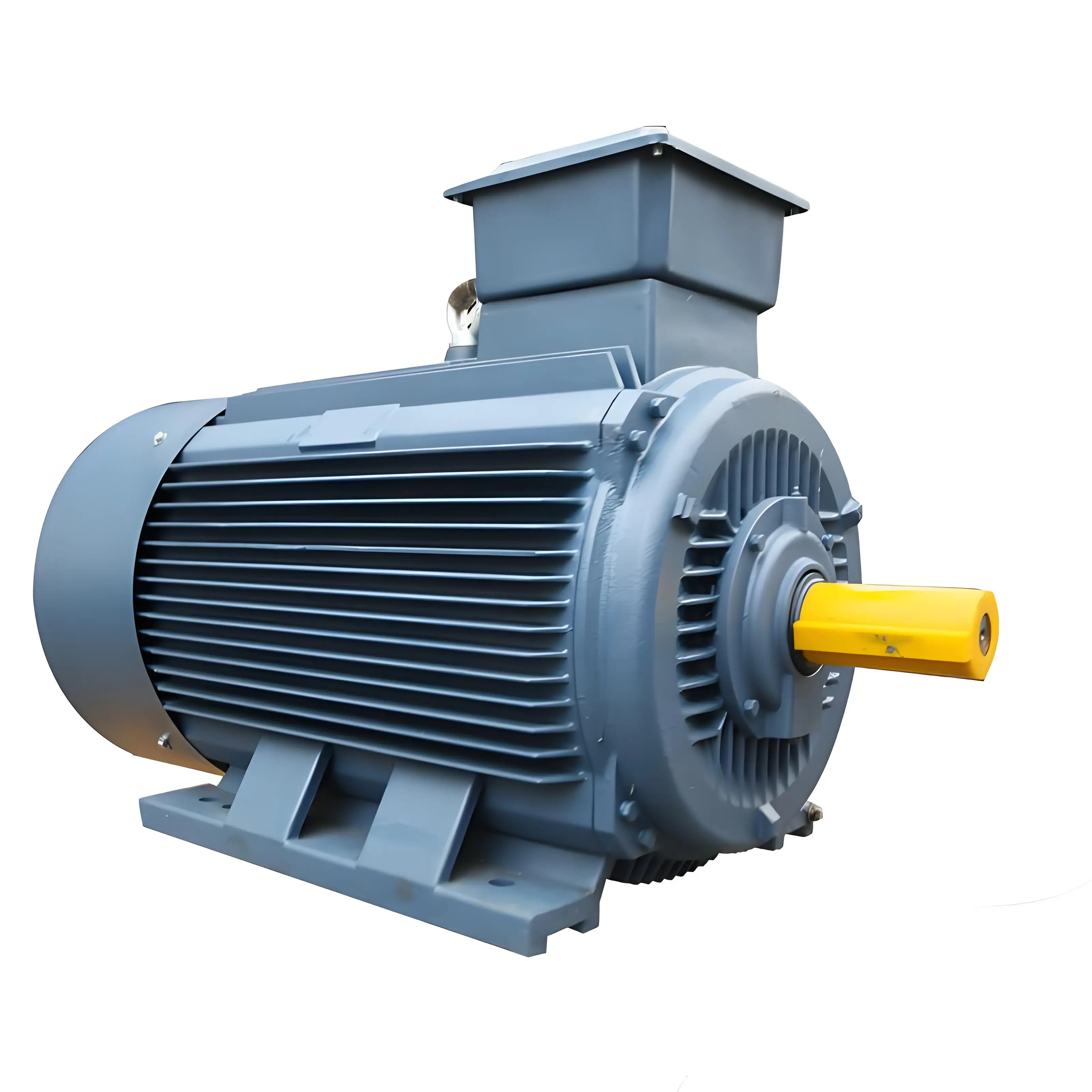
Speed reducers serve as the middlemen between electric motors and whatever machinery they power, helping to move energy around efficiently. Most electric motors spin pretty fast, usually somewhere between 1000 and 3000 revolutions per minute. But industrial applications often need much slower speeds. Take conveyor belts or mixing machines for example these typically work best when running under 100 RPM. That's where speed reducers come in handy. They let engineers adjust how fast the motor runs so it matches what the machine actually needs. Plus they help protect motors from getting damaged by too much force or wear and tear over time.
The basic idea behind gear reduction is pretty straightforward energy conservation stuff really. When something spins slower, it actually gets stronger in terms of torque. Take a 5 to 1 reduction ratio for example. That cuts down the speed by about four fifths but makes the torque five times what it was originally. This kind of trade off between speed and strength matters a lot in things like crane operations. The extra torque lets those cranes lift much heavier weights without putting too much strain on the motors themselves. Most modern gear setups today run at around 95 to almost 100 percent efficiency each time they change gears, so not much power gets lost in the process overall.
Motor speed reducers work by changing how fast something spins and how much force it can deliver through different sized gears. When a motor turns quickly on the input shaft, all that motion gets passed along through gears that aren't the same size. Take a small pinion gear turning a bigger gear, for instance. This setup slows things down based on how many teeth each gear has. Industry tests have found that when there's a 4 to 1 gear ratio, the output speed drops to just 25% of what went in, but the torque goes way up four times higher. This kind of power adjustment is really important for machines that need exact movements, especially in robotic arms and those computer controlled manufacturing tools we see everywhere these days.
Three key factors influence performance:
Modern systems increasingly use adaptive torque sensors to adjust engagement pressure dynamically, maintaining optimal efficiency across variable loads.
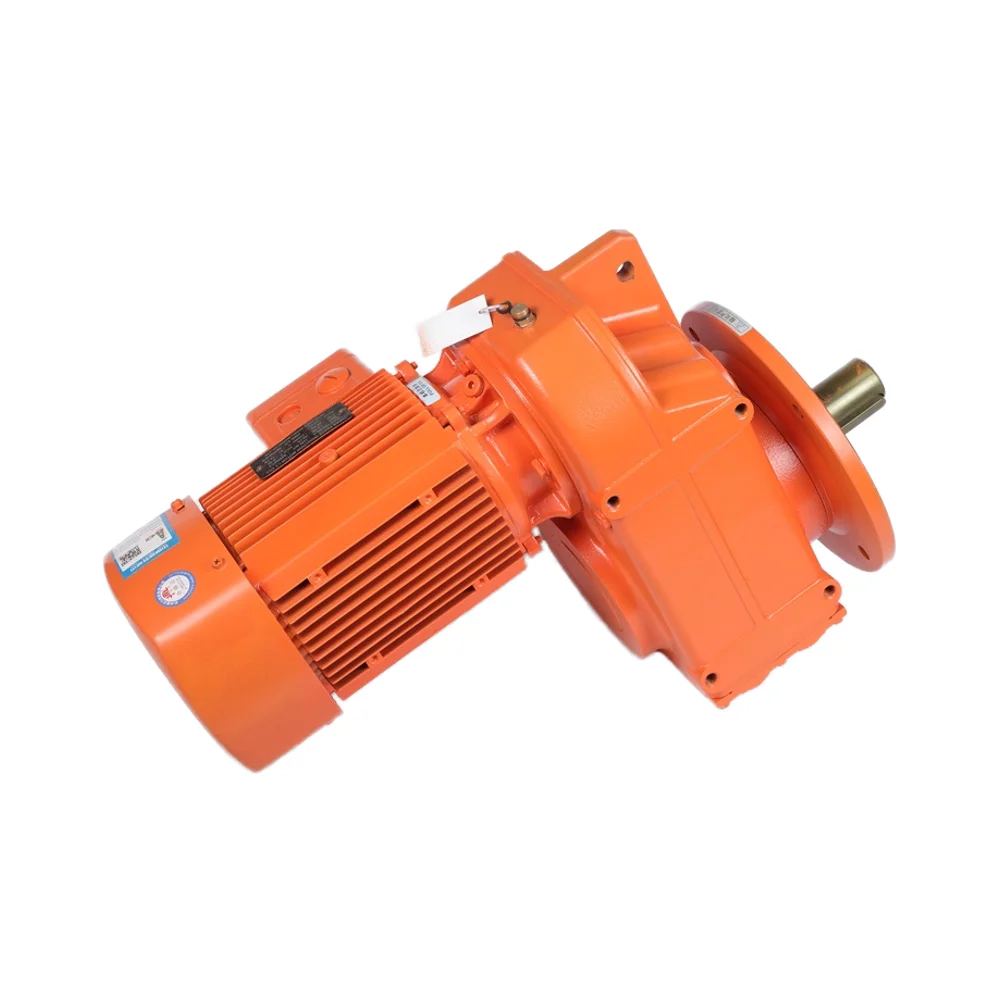
This transformation relies on staged gear reductions that progressively increase mechanical advantage. A typical industrial reducer might use multiple stages:
| Stage | Gear Ratio | Speed Reduction | Torque Gain |
|---|---|---|---|
| 1 | 5:1 | 80% | 5x |
| 2 | 4:1 | 95% | 20x |
As demonstrated in conveyor system implementations, this approach enables handling of heavy loads at speeds as low as 10 RPM while preserving motor longevity and efficiency. The final output delivers calibrated force ideal for slow, powerful operations such as crane hoisting or industrial mixing.
Gear reduction ratios basically tell us how a speed reducer changes the rotation speed and torque from one shaft to another. The calculation is pretty straightforward - just take the number of teeth on the input gear (T1) divided by those on the output gear (T2). This gives us what engineers call mechanical advantage. Let's say we have a 4:1 ratio. That means for every full turn of the output shaft, the input has to spin around four times. So the speed drops by about three quarters while the torque goes up four times over. Some folks get confused here because they might hear "transmission ratio" thrown around, which sometimes actually refers to the opposite calculation (output divided by input RPM). When working with machinery, higher gear ratios are great for getting more power out of motors when lifting heavy loads. On the flip side, lower ratios make sense when speed matters more than raw strength, like in precision cutting tools where control beats brute force.
These concepts are connected but have different meanings depending on how they're used. The gear reduction ratio, calculated as T1 divided by T2, basically shows how much torque gets multiplied through the system. Transmission ratio works differently though, often expressed as T2 over T1, and it tells us something about how fast things spin after going through gears. Getting these mixed up can cause real problems. A recent survey from the Global Mechanical Standards Consortium found that around one third of all maintenance mistakes last year came down to this very confusion. That's why engineers need to double check what exactly those numbers mean when reading technical specs for machinery.
When working with gear reductions, engineers typically use this basic formula: Gear Reduction Ratio (R) equals Input Teeth divided by Output Teeth. Let's say we have 56 teeth on the input gear and only 14 on the output side. That gives us a ratio of 4 to 1, which means torque gets multiplied roughly four times over in theory. But wait! Real world applications aren't so straightforward because machines lose some power through friction and other losses. Most helical gears operate around 85 to 95 percent efficiency in practice. So if someone wants to get 180 Newton meters at the output from a 5:1 reducer running at 90% efficiency, they actually need about 40 Nm going in. The math looks like this: take the desired output (180) and divide it by both the ratio (5) and the efficiency factor (0.9). Modern gearboxes equipped with Internet of Things technology handle all these complex calculations automatically now. These smart systems continuously adjust their gear ratios as conditions change, making sure everything runs smoothly even when load demands fluctuate throughout the day.
When it comes to torque amplification, we're basically talking about mechanical advantage in action. The principle works when a smaller gear turns a bigger one, which means we get more force but lose some speed in the process. Take a standard 3:1 gear reduction for example this setup will multiply torque three times over while slowing things down to just one third of the original speed. Research published by ASME back in 2023 found that good quality gear systems can actually hit around 95% efficiency levels, meaning very little gets lost as heat or friction during operation. There's even a handy formula engineers use all the time: Torque Out equals Torque In multiplied by Gear Ratio and then multiplied again by Efficiency. This calculation helps match power requirements precisely across different applications such as modern robotics and increasingly popular electric vehicles where every bit of energy counts.
In many industrial settings, getting the right balance between speed and torque is absolutely essential. Take material handling equipment as an example these systems need plenty of torque to lift heavy loads even if that means moving slower. According to research funded by NASA back in 2022 looking at warehouse automation setups, they discovered that using a 5 to 1 gear ratio made conveyor belts work much better, reducing stress on motors by about 40 percent. When designing such systems, engineers really need to focus on three main things first, how much weight the system can handle at its peak, second, how long it needs to run continuously before resting, and third, making sure there's minimal play in the gears so positioning stays accurate. The good news is newer variable ratio reducers let operators adjust performance parameters on the fly, which means a single machine can handle different tasks throughout the day without anyone needing to swap out parts or reconfigure hardware completely.
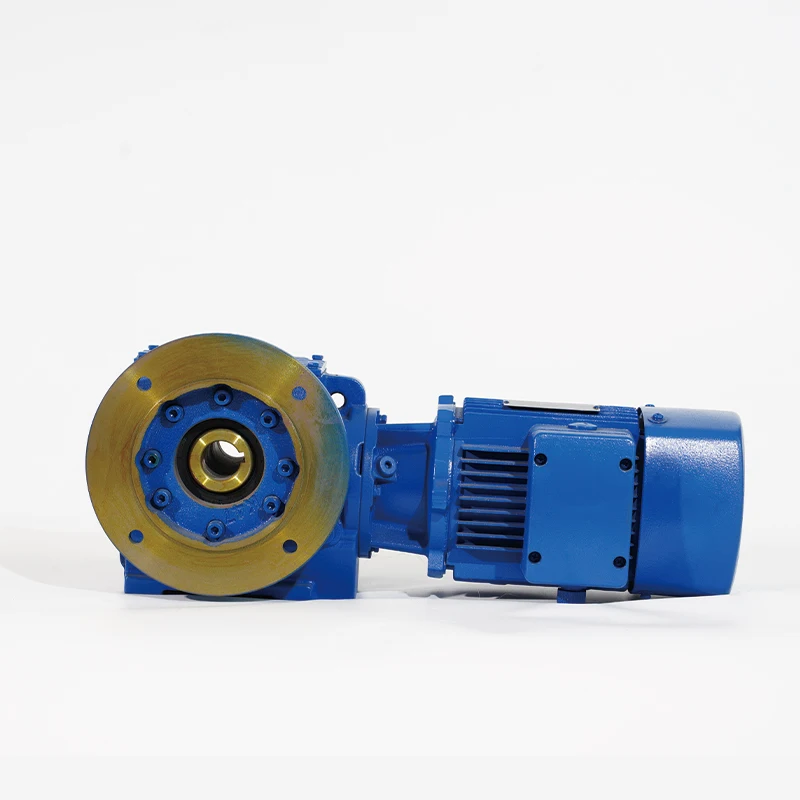
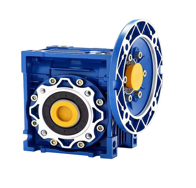
A manufacturing plant upgraded its assembly line with right-angle gear reducers to eliminate recurring motor burnouts. Implementing a 7.5:1 reduction ratio resulted in:
| Metric | Before | After | Improvement |
|---|---|---|---|
| Torque (Nm) | 120 | 840 | 7Ã |
| Motor RPM | 1,750 | 250 | â |
| Energy Use/Hour | 4.2 kWh | 3.1 kWh | 26% reduction |
The upgrade eliminated gear slippage and extended bearing lifespan by 300 hours annually, demonstrating how properly selected speed reducers improve both reliability and energy efficiency.
Speed reducers are indispensable in manufacturing, adapting motor outputs to meet specific machine requirements. They enable conveyors to move heavy loads at controlled speeds, prevent motor overload, and enhance process stability. Common applications include:
| Application | Function | Benefit |
|---|---|---|
| Robotic arms | Precision positioning | ±0.01 mm repeatability |
| Mixing equipment | Consistent torque delivery | 20–30% longer bearing lifespan |
| Packaging systems | Speed synchronization across stations | 15% higher throughput |
A 2024 analysis of industrial automation trends revealed that 78% of production line failures stem from mismatched speed or torque parameters, reinforcing the critical role of speed reducers in system reliability. This aligns with the International Federation of Robotics' projection that over 500,000 industrial robots will require precision gear reducers by 2025.
Advanced designs using helical and planetary gears achieve motion accuracy within 5 arc-minutes. In CNC machining centers, this supports spindle speeds exceeding 8,000 RPM with positional deviations under 5 µm. Wind turbine manufacturers now deploy adaptive reducers that dynamically compensate for backlash, reducing gear wear by up to 40% compared to fixed-tolerance models.
The rise of IIoT-connected reducers has driven a 200% increase in predictive maintenance adoption since 2020. Integrated vibration sensors and thermal imaging enable:
According to a 2024 robotics market report, 63% of new industrial robots now feature smart reducers with machine learning interfaces, allowing self-optimization of gear meshing patterns under changing operational conditions.
 Hot News
Copyright © 2025 by Changwei Transmission (Jiangsu) Co., Ltd — Privacy Policy