Motor speed reducers work as mechanical systems driven by gears to transform the fast spinning, weak power from motors into something slower but much stronger. The whole thing works because of how different sized gears fit together. When a small gear turns a bigger one, what happens is pretty straightforward physics stuff: the rotation slows down but the force gets multiplied. Take a 10 to 1 gear ratio for instance. That basically means the motor has to spin around ten full times just to make the output shaft turn once, but when it does, it packs ten times more punch. Conveyor belts really benefit from this setup since they need to move heavy stuff without burning out the motors underneath them all the time.
When it comes to speed reducers, there's basically an opposite relationship between how fast something spins (RPM) and the twisting force it can produce (torque). Cut the output speed in half, and suddenly you've got twice as much torque available. Take a motor that normally runs at 1,000 RPM with 5 Newton meters of torque for instance. With a 10:1 reducer gear, that same motor can slow down to just 100 RPM while delivering a whopping 50 Nm of torque instead. This kind of power conversion makes all the difference in heavy machinery like industrial presses and rock crushers. These machines need massive amounts of torque but at slower speeds to avoid frying motors. We've seen field data indicating that when manufacturers get the reducer sizing right, their equipment lasts about 60% longer under tough loading conditions than systems that try to run everything directly off the motor without any reduction gears involved.
Gear ratios basically tell us how input revolutions relate to output revolutions, and they really determine how well a system performs. When we talk about high ratios like 20 to 1, these are all about getting maximum torque, which is why they work so well in heavy-duty machinery such as rock crushers. On the flip side, lower ratios around 3 to 1 keep things moving at a reasonable pace, making them perfect for stuff like packaging lines where continuous motion matters more than brute strength. Most engineers know the drill: Output Torque equals Motor Torque multiplied by Gear Ratio. This helps figure out if the reducer can handle what's being asked of it. And let's face it, even a small mistake here counts. We've seen cases where just a 15% error in selecting the right ratio leads to a massive 35% drop in efficiency during those repetitive cycles. That's why getting these numbers right from day one remains absolutely critical in industrial settings.
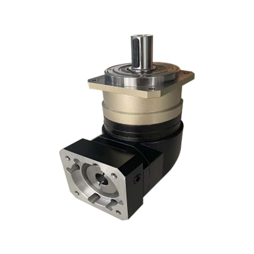
Planetary gear reducers work by having several smaller gears rotate around a central sun gear, which allows them to pack a lot of power into small packages while maintaining good alignment. This compact nature is why they're so popular in robotic arms and automated machinery where space is at a premium but precision matters most. A recent study from Mechanical Systems Analysis found that these types of reducers can hit around 97% efficiency when dealing with heavy loads because the forces get spread out over multiple gear contacts instead of concentrating on just one point. For manufacturers looking to optimize their equipment performance without taking up too much room, planetary reducers offer both strength and smart engineering all wrapped up in a neat little package.
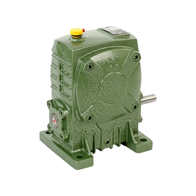
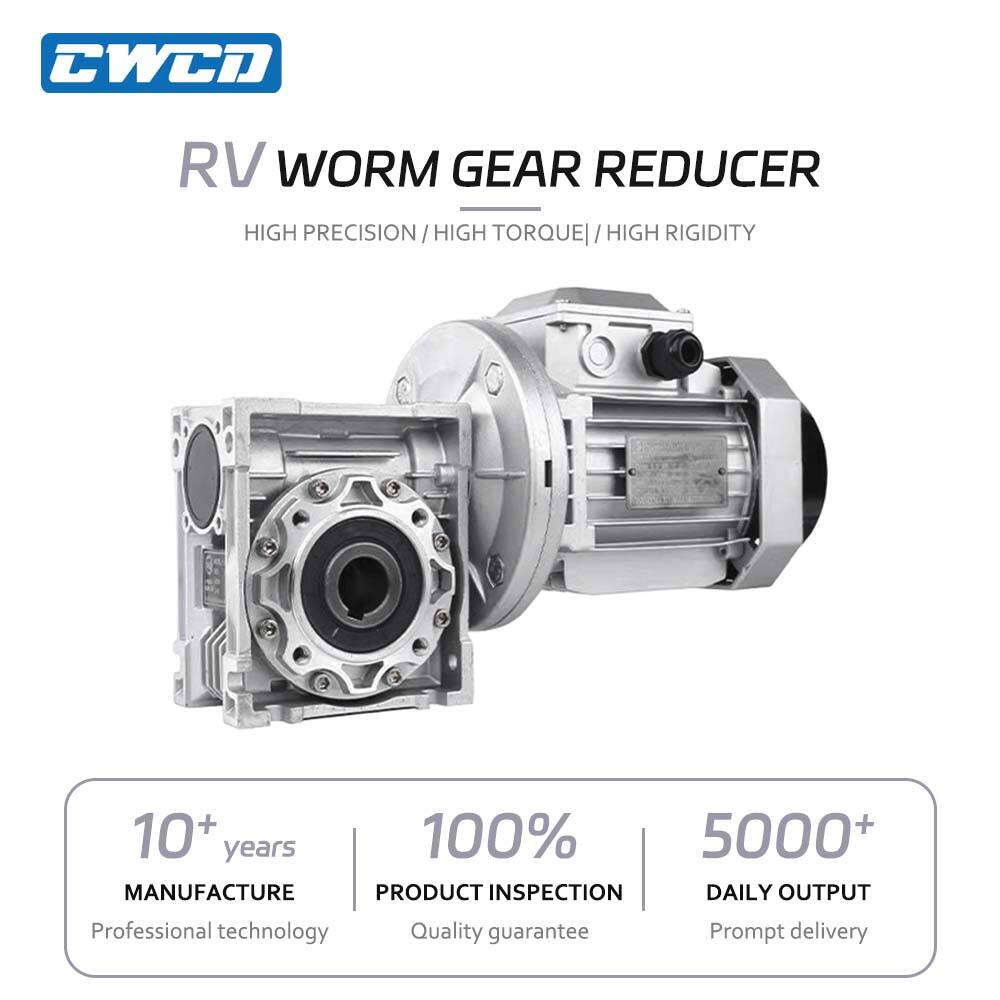
Worm gear systems work by having a threaded screw, often called a worm, that meshes with a toothed wheel. These setups can get reduction ratios over 100:1 in just one stage. What makes them stand out is this built-in self-locking feature that stops things from turning backward. That's why they're so good for things like conveyor belts and lifting gear where unexpected movement could be dangerous. Sure, they aren't as efficient as planetary gears, maybe around 65 to 85 percent efficiency depending on conditions. But what they lose in efficiency they make up for in reliability. The fact that there's no slipping means these gears stay put when needed most, especially important when dealing with loads hanging vertically.
Bevel gears change the direction of shaft rotation at right angles thanks to their cone-shaped teeth, whereas helical gears have teeth cut at an angle which allows them to mesh more smoothly when shafts run alongside each other. Both types find plenty of use in heavy machinery across mines and construction sites because they transfer power at angles that help protect other parts from excessive wear over time. The helical version actually runs about 15 percent quieter compared to standard spur gears since the teeth come into contact gradually instead of all at once, making these gears ideal for environments where noise levels matter a lot during operations.
Material handling systems rely heavily on worm gear reducers because they deliver that crucial combination of high torque and self-locking features which stops things from rolling back down those incline conveyors. Some tests run by the Material Handling Institute showed that when using hardened steel bevel gears instead of helical ones in cross conveyor setups, efficiency jumped around 30%. That makes a big difference over time. Industrial workers know these reducers can take a beating too. They hold up under massive loads in mines and packaging operations despite all the constant movement. Most models manage to keep running at pretty decent efficiencies between 85% and 92%, which is actually quite impressive considering what they go through day after day.
Planetary gear reducers are pretty much essential for getting those robotic arms and CNC machines to work with real precision. They cut down on backlash to around plus or minus one arc minute while spreading out the torque across several gear teeth at once. The space saving design means these gears pack quite a punch when it comes to power density too about five to ten times better than regular worm gears. That makes them ideal for collaborative robots that need to handle weights of up to twenty kilograms without breaking a sweat. And speaking of demand, we're looking at some serious growth here. According to the International Federation of Robotics, they expect somewhere around half a million industrial robots will be put into service worldwide by 2025. Makes sense given how much manufacturing is changing right now.
Hardened helical gear reducers last over 50,000 hours in crushers and extruders when dealing with shock loads that go beyond 200% of normal torque levels. They achieve this longevity thanks to their tapered roller bearings and the right kind of ISO VG 320 lubricants. Field testing done recently according to ASTM standards found something interesting too. These modern reducers keep running at around 98% efficiency even when temperatures hit 150 degrees Celsius. That's pretty impressive compared to the old parallel shaft designs which typically lag behind by about 12 percentage points in actual cement mill operations across the industry.
When looking at mechanical systems, start with understanding what kind of torque requirements exist along with how inertia forces will affect operation. The choice of gear ratios makes a big difference in what the system can actually deliver. Higher gear ratios generally mean more torque available at the expense of reduced rotational speed. Take helical gear reducers as an example case study. A standard 10 to 1 ratio configuration typically increases torque output around nine and a half times compared to input, though this comes with about half the original speed. Such setups work really well for those heavy duty conveyor belts we see in industrial settings. Industry professionals consistently point out that proper sizing matters a lot. Most problems come from not accounting for both maximum load conditions and regular operating loads. Undersized components account for roughly two thirds of all early failure incidents seen in material handling equipment across different manufacturing sectors.
Reducers in food processing or marine environments require IP65+ sealing and corrosion-resistant materials like stainless steel. Dust-heavy settings demand labyrinth seals, while washdown areas need lip seals rated for 150+ PSI. Research shows improper sealing accounts for 52% of lubricant contamination failures.
Mismatched mounting interfaces cause 41% of vibration-related breakdowns. Verify:
High-precision planetary reducers achieve 94–97% efficiency but cost 2–3x more than worm gear models. Use lifecycle cost models comparing:
| Factor | Short-Term Focus | Long-Term Focus |
|---|---|---|
| Initial Cost | $1,200–$2,500 | $3,000–$6,000 |
| Efficiency Loss | 15–25% | 3–8% |
| Maintenance Cycles | 6–12 months | 24–36 months |
Industry benchmarks reveal a 19% ROI improvement when prioritizing service factor (1.5+ for shock loads) over upfront savings.
 Hot News
Copyright © 2025 by Changwei Transmission (Jiangsu) Co., Ltd — Privacy Policy