Speed reduction motors combine electric motors with gear reducers to cut down on rotational speed but boost torque output at the same time. The basic idea is pretty straightforward mechanical advantage stuff really. When gears with different numbers of teeth mesh together, they slow things down just like how bicycle gears make pedaling easier or harder depending on what gear you're in (as noted by Cotta back in 2024). Take a 10:1 gear ratio for instance it basically cuts the output speed by ten times but makes the torque much stronger in return. Some recent studies from 2023 looking at electro mechanical systems found that these industrial versions can actually crank up torque by nearly double what regular motors manage on their own. What do these motors actually do? Well, among other things they:
The primary components work together to achieve speed-torque conversion:
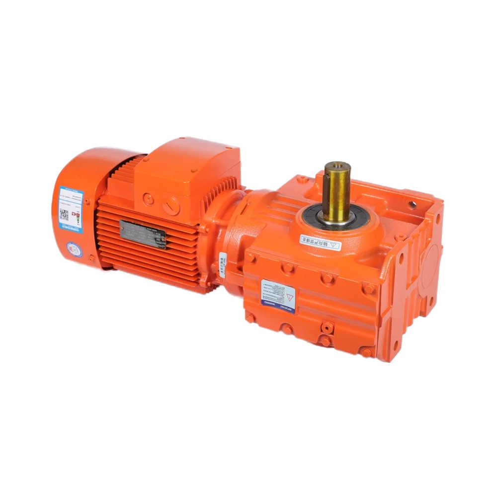
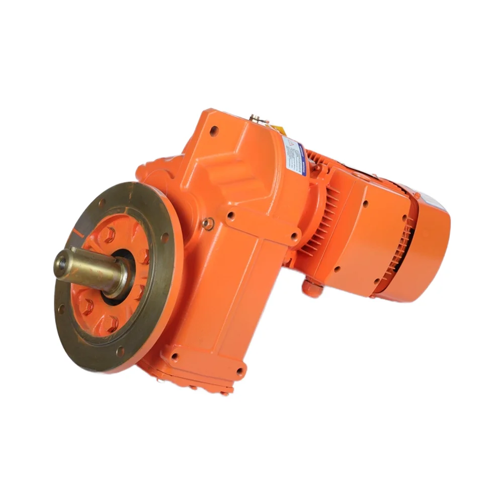
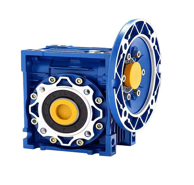
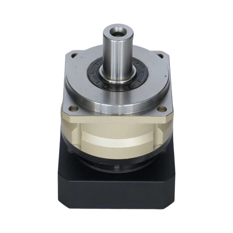
Gearboxes act like the transmission of a mechanical system, basically taking power from one place and delivering it somewhere else at just the right speed and force needed for whatever job it needs to do. Worm gear reducers are great when space is limited because they pack quite a punch in terms of torque despite their small size. Planetary gears work differently by spreading out the load over several points which makes them last longer under heavy duty conditions. When designing machinery, engineers tweak these different gear setups so they get exactly what they need - usually reducing speeds anywhere from 3 times down to 100 times slower than original input while still maintaining enough power output without having to change anything about the main motor itself.
The way gears work basically boils down to trading off speed against power. Take a gear set with a 5 to 1 ratio for instance. What happens here is the output shaft turns five times slower than what comes in from the input side, but it packs five times the punch in terms of torque. The math behind it goes something like Output Torque equals Input Torque multiplied by the Gear Ratio. Some recent research published last year looked at this exact phenomenon. They tested a motor running at 1000 revolutions per minute connected through a 10 to 1 gear reduction. Suddenly that same motor was only turning at 100 RPM, yet the torque jumped all the way from 2 Newton meters up to 20 Nm. This kind of tradeoff means mechanical engineers can fine tune their designs depending on whether they need maximum force for delicate movements or just want things moving quickly without worrying about strength.
To figure out the reduction ratio (R), we use this formula: $$ R = \frac{\text{Number of Teeth on Driven Gear (T2)}}{\text{Number of Teeth on Driving Gear (T1)}} $$ Take for example when someone has a driving gear with 15 teeth connected to a driven gear with 45 teeth. That gives us a 3 to 1 ratio. When gears have higher ratios above 10 to 1, they work best where lots of twisting force matters, think about big machines that crush rocks in quarries. On the flip side, gears with ratios below 3 to 1 are better suited for fast moving stuff, like those computer controlled machines used in manufacturing parts for cars and electronics.
Recent tests evaluated three gear types lifting a 500 kg load:
| Gear Type | Efficiency | Max Torque | Lifespan (Hours) |
|---|---|---|---|
| Spur | 93% | 180 Nm | 8,000 |
| Helical | 95% | 210 Nm | 12,000 |
| Planetary | 98% | 250 Nm | 15,000 |
Planetary gears delivered superior torque and longevity, justifying their higher initial cost in heavy-duty machinery.
When it comes to gearboxes, they basically boost torque using those gear ratios we all know about. The output force goes up as the speed drops down. Take a 10 to 1 ratio for instance. That means torque gets multiplied by ten times but speed takes a big hit, dropping around 90%. This is why even tiny motors can handle pretty heavy stuff when connected through gears. The reason behind this mechanical trick? It's all about how energy works. When something slows down (less kinetic energy), that energy gets converted into more twisting power (potential energy). So instead of needing huge motors, manufacturers can use smaller ones that still manage to lift things way heavier than what they could do on their own.
In conveyor systems, a 1000 RPM motor combined with a 20:1 planetary gearbox produces 50 RPM and 9,500 N·m of torque—sufficient to move palletized goods at 2 m/s. Engineers often select helical gear designs for their 98% torque transmission efficiency, which minimizes energy loss compared to spur gears operating at 92%.
Key factors influencing torque efficiency include:
Tests conducted independently found that nearly one quarter of commercial gear motors only manage to produce 80% or less of what they claim on paper when actually put to work. Looking at data from a recent check of twelve different manufacturers in 2024, planetary gearboxes came closest to meeting specs with an average performance around 94%. The worm gear units told a different story though, falling short by almost 20%. Mechanical engineers across the industry are pushing harder for companies to follow ISO 21940-11 standards during testing. This would create consistent benchmarks for measuring torque output and help buyers know exactly what they're getting before making purchases.
The inverse relationship between speed and torque is governed by the law of energy conservation: power remains constant (Power = Speed à Torque à Constant). Thus, a 40% reduction in speed yields a 66% increase in torque. Industrial data illustrates this effect clearly:
| Gear Ratio | Speed (RPM) | Torque (Nm) |
|---|---|---|
| 5:1 | 1,200 | 18 |
| 10:1 | 600 | 36 |
| 20:1 | 300 | 72 |
This predictable scaling enables precise engineering of motor systems for targeted applications.
To balance speed and torque, engineers use:
Integrated systems have demonstrated 88% fewer speed fluctuations under variable loads compared to single-stage designs (DOE 2018), improving process consistency in dynamic environments.
Lab tests highlight performance differences across gear types:
| Motor Type | Peak Torque (Nm) | Stall Speed (RPM) | Efficiency Peak |
|---|---|---|---|
| Spur Gear | 50 | 80 | 82% @ 20Nm |
| Planetary Gear | 120 | 35 | 91% @ 45Nm |
| Cycloidal Drive | 300 | 12 | 84% @ 220Nm |
Electromate's torque analysis confirms planetary gears maintain â¥85% efficiency across 85% of their torque range, outperforming alternatives in sustained high-load operations.
In heavy duty equipment where machines need to handle shocks and maintain position when stopped, worm gears tend to be the go to choice. Their efficiency usually falls somewhere between 60% and maybe 90%, though this depends a lot on how good the lubrication is maintained. On the other hand, planetary gears shine in high precision work such as robotic arms or computer controlled machining centers. These systems typically hit around 95% efficiency because they distribute loads across multiple points instead of relying on just one contact area. When selecting gear types for industrial applications, engineers have to consider factors like available installation space, expected load weights, and how often the system will run continuously versus intermittently throughout shifts.
Today's assembly lines are starting to combine servo motors with built-in speed reducers for positioning accuracy down around 0.01 degrees. According to some recent findings from the Global Motor Tech Report for 2025, plants that hooked up torque controlled gear motors with their SCADA systems managed to cut down on wasted energy by about 18 percent. Pretty impressive considering they kept right along at 120 cycles every minute too. What makes these configurations work so well is how they can coordinate all those moving parts together across conveyors, robotic arms, and even pressing stations without ever pushing past their torque limits. Makes sense when thinking about maintaining consistent quality throughout the whole production process.
Advances in sintered metal alloys and helical gear profiling now allow 50mm³ gear motors to generate 12 N·m of torque—matching units three times larger just five years ago. Key innovations include:
These developments support miniaturization in medical devices, drones, and portable automation tools.
A European automotive plant reduced welding robot downtime by 40% after adopting backlash-free harmonic drives in 6-axis arms. These reducers maintained 0.5-arcmin rotational precision over 2 million cycles, ensuring consistent weld placement on EV battery trays despite payload variations from 5–22 kg.
Next-generation gearboxes integrate IoT sensors to monitor critical parameters in real time:
| Parameter | Monitoring Frequency | Industry Impact |
|---|---|---|
| Tooth wear patterns | Every 10,000 cycles | 22% reduction in unplanned maintenance |
| Lubricant viscosity | Real-time | 15% longer oil change intervals |
| Torque ripple | 100 Hz sampling | 8% improvement in stamping consistency |
Machine learning algorithms now predict gear tooth fatigue with 89% accuracy by analyzing vibration and thermal data. This shift toward condition-based maintenance could save mid-sized manufacturers $740,000 annually in motor replacement costs (Ponemon 2023).
Speed reduction motors are used to adapt high-speed motor output to slower, high-torque applications, protect motors from overload stresses, and enable precise motion control in automated systems.
Gear ratio affects speed and torque by allowing the output shaft to turn slower or faster than the input while either increasing or decreasing torque, respectively.
Common types of gears used in speed reduction include spur gears for low-noise applications, helical gears for smooth, quiet engagement, and planetary gears for high torque density and reliability.
Gearboxes increase torque by using gear ratios that lower speed but boost torque output, allowing smaller motors to handle heavier loads.
Factors influencing torque amplification efficiency include gear type, lubrication quality, and proper alignment.
 Hot News
Copyright © 2025 by Changwei Transmission (Jiangsu) Co., Ltd — Privacy Policy