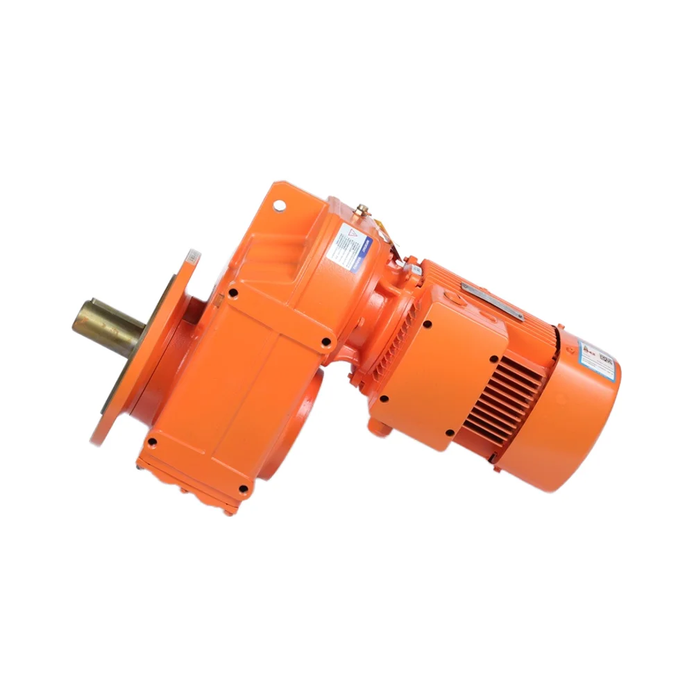
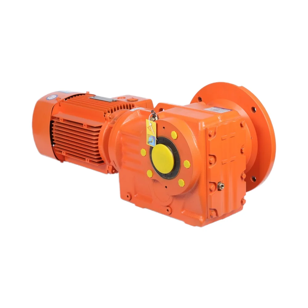
Worm gear boxes work by converting rotational movement using a special kind of meshing action between the worm (which is basically the input shaft) and the wheel gear. These systems can achieve impressive speed reductions of around 100:1 in just one stage according to recent industry reports from 2024 on mechanical transmission. What makes them different from standard spur or helical gears is their sliding contact mechanism that actually multiplies torque at an exponential rate all while keeping things compact. This makes them particularly useful in tight spaces like conveyor belts, robotic arms, and various types of heavy equipment where there simply isn't room for larger components.
When it comes to worm gears, their helical angle actually creates this built-in locking feature that stops things from moving backward when everything's sitting still. This means no worries about back driving in stuff like vertical lifts or hospital beds, which makes these systems safer without needing extra brakes all over the place. Some studies have found that when steel and bronze gears are well lubricated, they stop unwanted movement about 98 out of 100 times. That kind of reliability matters a lot for equipment that needs to hold loads securely in position.
Sliding contact between gear teeth reduces vibration by 40–60% compared to rolling-contact gears (Gear Dynamics Study 2023). Combined with precision-ground tooth profiles, this makes worm gear boxes ideal for hospital equipment, packaging lines, and lab automation systems requiring 60 dB noise levels.
Worm gears are great at multiplying torque but come with a downside because of all that sliding friction which brings down mechanical efficiency somewhere between 50% and 90%. This actually depends quite a bit on how well they're lubricated and what kind of lead angle we're talking about. Most engineers try to work around this issue when designing systems. They usually cap gear ratios at around 60 to 1 for things that need to run fast. Synthetic oils help cut down those pesky friction losses by roughly 15% to 20%. And for longer lasting performance, many go with hardened steel worms combined with bronze wheels since this combination stands up better to wear and tear over time.
Getting the right gear ratio means finding that sweet spot between slowing things down and boosting power output. Take systems that need serious starting torque for instance, conveyor belts and elevators typically work best with ratios ranging from around 10 to 60. When it comes to really precise movements, think medical robots here, engineers often go for ratios as high as 100 to 1. These allow those tiny, controlled motions without making the whole system too big. The math gets interesting when matching gears to motor speeds. If someone has a 10 horsepower motor connected to a 30 to 1 gearbox, they can generally expect to handle about 75 pound feet of load. But crank that ratio up to 50 to 1, and suddenly that same motor drops to handling only 45 pound feet before getting overloaded.
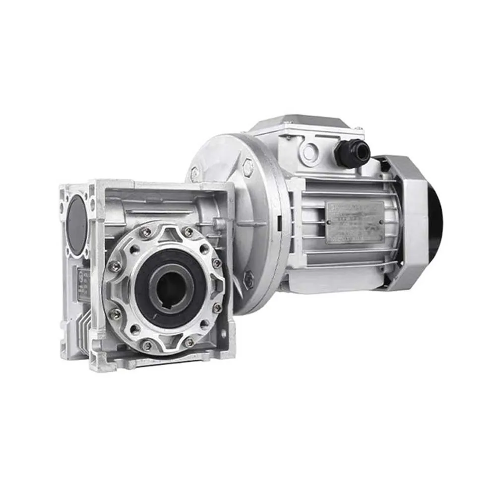
Output shaft designs directly impact installation flexibility. Hollow bore configurations simplify direct motor coupling in confined spaces, while double shafts enable bidirectional power transmission for rotary indexing tables. Center distances (typically 25–200mm) must align with frame dimensions—a ±0.5mm tolerance prevents axial misalignment that accelerates wear.
Getting torque calculations right means accounting for both static and moving forces in the system. According to AGMA 6034 guidelines, engineers should generally apply safety multipliers ranging from 2 to 10 times the operating torque based on how critical the application is. Medical equipment lifts typically get the 5x treatment since they need to hold up during unexpected emergency stops when lives are at stake. Take a standard packaging line moving around 100 kg loads as an example case study. The worm gearbox there needs at least 300 Nm rating capacity just to handle those occasional jams that happen in production environments. Looking across various industry reports, roughly two thirds of early gear failures actually trace back to folks not properly considering those sudden spikes in dynamic load conditions during design phase.
| Gear Type | Efficiency Range | Common Applications |
|---|---|---|
| Single-Thread | 30–50% | Lifts, Safety Brakes |
| Multi-Thread | 65–85% | Conveyors, HVAC Systems |
| Hollow Bore | 70–90% | Robotics, Precision Machinery |
Hardened steel worms paired with bronze wheels dominate industrial applications, offering 15% higher efficiency than aluminum alternatives. Recent advancements in polymer composites show promise for food-grade environments, reducing lubrication needs by 40% while maintaining 80% efficiency.
Worm gear boxes tend to wear out much faster when operating in places where temperatures go over 120 degrees Fahrenheit or the air gets really humid, say around 80% relative humidity and up. Take food processing facilities for instance they need those special IP65 rated enclosures so water from cleaning doesn't get inside during washdowns. Then there are boats and ships where saltwater is everywhere, so engineers have to use stainless steel bolts instead of regular ones to fight off corrosion from sea spray. Dust particles in cement manufacturing plants can be particularly damaging too. These tiny bits of concrete dust sneak into gearboxes and reduce their efficiency by somewhere between 12 to 18 percent every year if the seals aren't good enough according to last year's Industrial Drives Report. That kind of loss adds up fast for plant managers watching their bottom line.
Phosphor bronze worms paired with hardened steel gears are ideal for moderate loads, offering 85–92% efficiency. For corrosive environments like wastewater treatment, aluminum-bronze alloys extend service life by 3–5x compared to standard steel. High-torque scenarios (>1,000 Nm) necessitate case-hardened alloy steel components to withstand cyclic stress without micro-pitting.
PAO based synthetic greases keep their viscosity across pretty extreme temperatures, from about -40 degrees Fahrenheit all the way up to around 300 degrees F. That makes them really important for equipment used in mining operations outdoors where temps can swing wildly. Recent research published last year showed something interesting too. When maintenance crews stick to regreasing every 2,000 to 3,000 hours on those continuous duty machines, they actually see a drop of nearly two thirds in wear particles generated. Pretty impressive stuff when thinking about long term component life. As far as matching the right grease goes, it's generally wise to pair NLGI grades with how fast things are spinning. Most standard #2 grease works well for slower moving parts below 100 RPM while the thinner #1 grade handles the faster applications above 500 RPM much better.
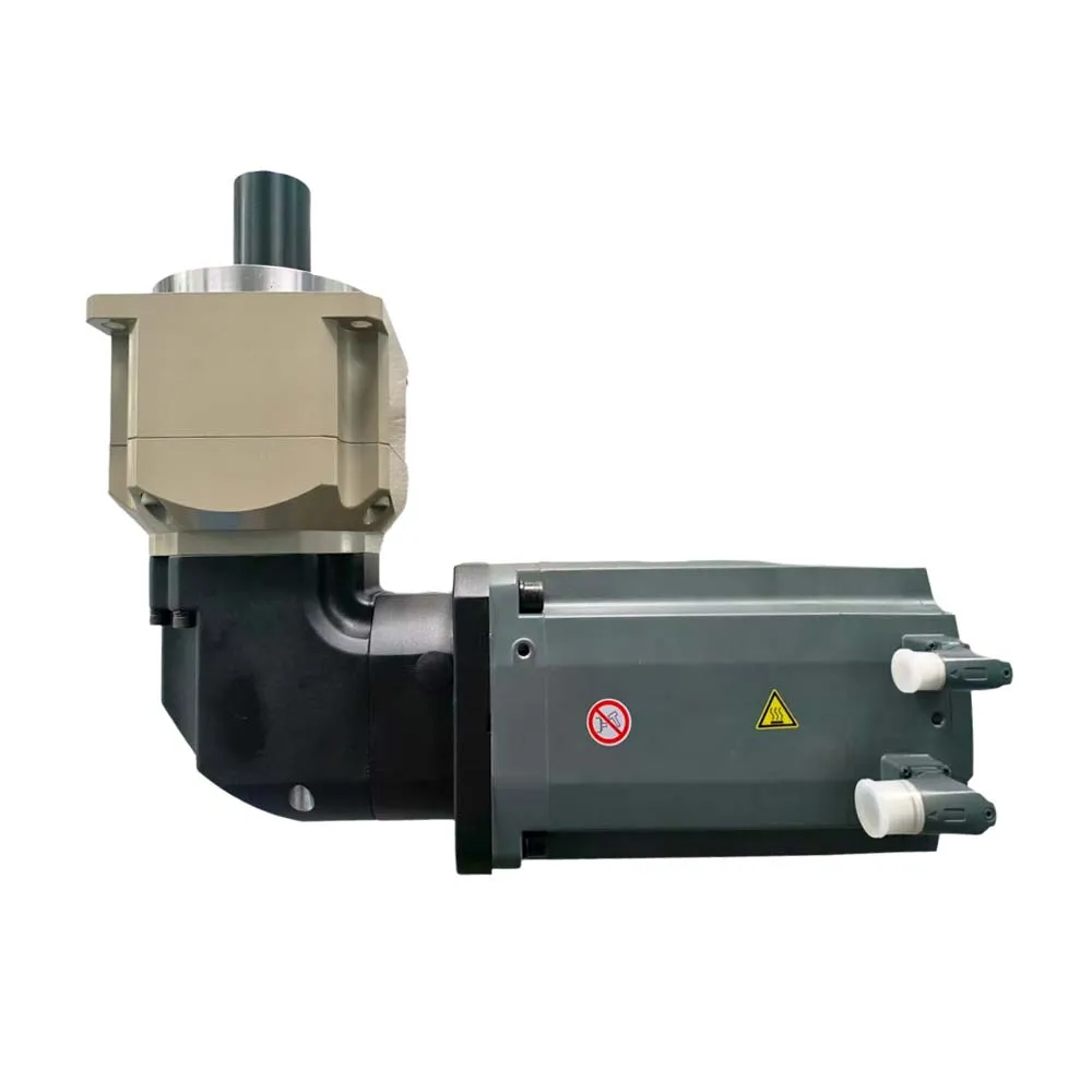
Getting motor and gearbox combinations right begins with making sure their speed inputs and torque demands line up properly. Worm gearboxes are particularly good at slowing down motor outputs significantly, sometimes by as much as 100 times, while boosting torque accordingly. Take for example a standard motor putting out around 10 Newton meters at 1,750 revolutions per minute. With a 100:1 reduction ratio, this same motor could generate approximately 1,000 Newton meters of torque at just 17.5 RPM instead. Before finalizing any setup, it's important to check that the motor's power specifications actually fit what the gearbox expects as input to avoid damaging either component. There are several key considerations worth keeping in mind too. First off, make certain the voltage and frequency match between components, especially when dealing with different regional standards like 50 versus 60 Hertz supplies. Also pay attention to startup torque requirements since these worm gear systems typically need two to three times their normal operating torque when first getting going. Lastly, think carefully about duty cycles so they accurately represent both the maximum and ongoing torque demands according to how loads will behave over time.
When there's a mismatch between motor and gearbox inertia, it creates unwanted oscillations that mess with positioning accuracy in automation setups. Looking at what manufacturers have found, keeping the inertia ratio (gearbox divided by motor) under about 10 to 1 makes motion control respond better, somewhere around 40 to maybe even 60 percent improvement in some cases. These days, worm gearboxes come with built-in encoders which makes them much easier to sync up with servo drives and PLC systems. This is especially handy for those working on Industry 4.0 projects where predictive maintenance features are becoming standard requirements across many manufacturing facilities.
| Feature | Hollow Bore | Solid Shaft |
|---|---|---|
| Installation | Direct motor shaft mounting | Requires coupling/flange |
| Space Efficiency | 30–50% shorter assembly length | Needs lateral mounting space |
| Torque Capacity | Up to 850 Nm (standard models) | 1,200+ Nm (heavy-duty) |
| Ideal For | Conveyors, packaging lines | Cranes, industrial mixers |
Hollow bore configurations dominate food processing and pharmaceutical applications (75% adoption) due to washdown-friendly designs. Solid shafts remain preferred for mining equipment where shock loads exceed 500% of nominal torque.
Worm gear boxes work really well in material handling setups when there's limited space but lots of torque is needed. The small footprint makes them ideal for powering those conveyor belts that move heavy stuff around automotive factories. Plus, their self locking feature keeps elevators steady at whatever position they need to be in, no extra brakes required. Some research from the construction machinery field back in 2023 showed interesting results too. They found that warehouses using worm driven lifting systems actually saved about 18 percent on energy costs compared to similar setups with helical gears instead. Makes sense why so many operations are switching over these days.
The sliding contact mechanism in worm gears operates 40% quieter than spur gear systems, making them ideal for noise-sensitive food processing plants. Stainless steel variants meet hygienic standards for packaging machines that seal 500+ containers per minute. Industry reports show their corrosion-resistant coatings extend service life by 60% in high-moisture bottling facilities.
Worm gearboxes provide sub-millimeter accuracy in MRI table adjustments and radiotherapy positioning arms. The irreversible motion prevents accidental back-drive—a critical safety feature when handling sensitive medical instruments.
Opt for worm gear systems when footprint constraints exist or vertical loads require fail-safe holding. Their self-locking design eliminates costly brake systems in 92% of inclined conveyor applications, while single-stage units achieve 50:1 reduction ratios in spaces under 8 cubic inches.
 Hot News
Copyright © 2025 by Changwei Transmission (Jiangsu) Co., Ltd — Privacy Policy