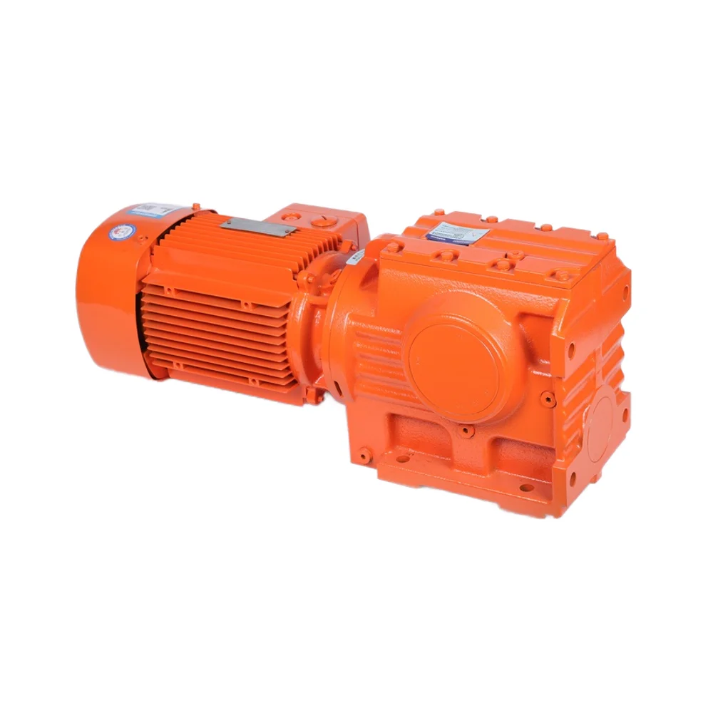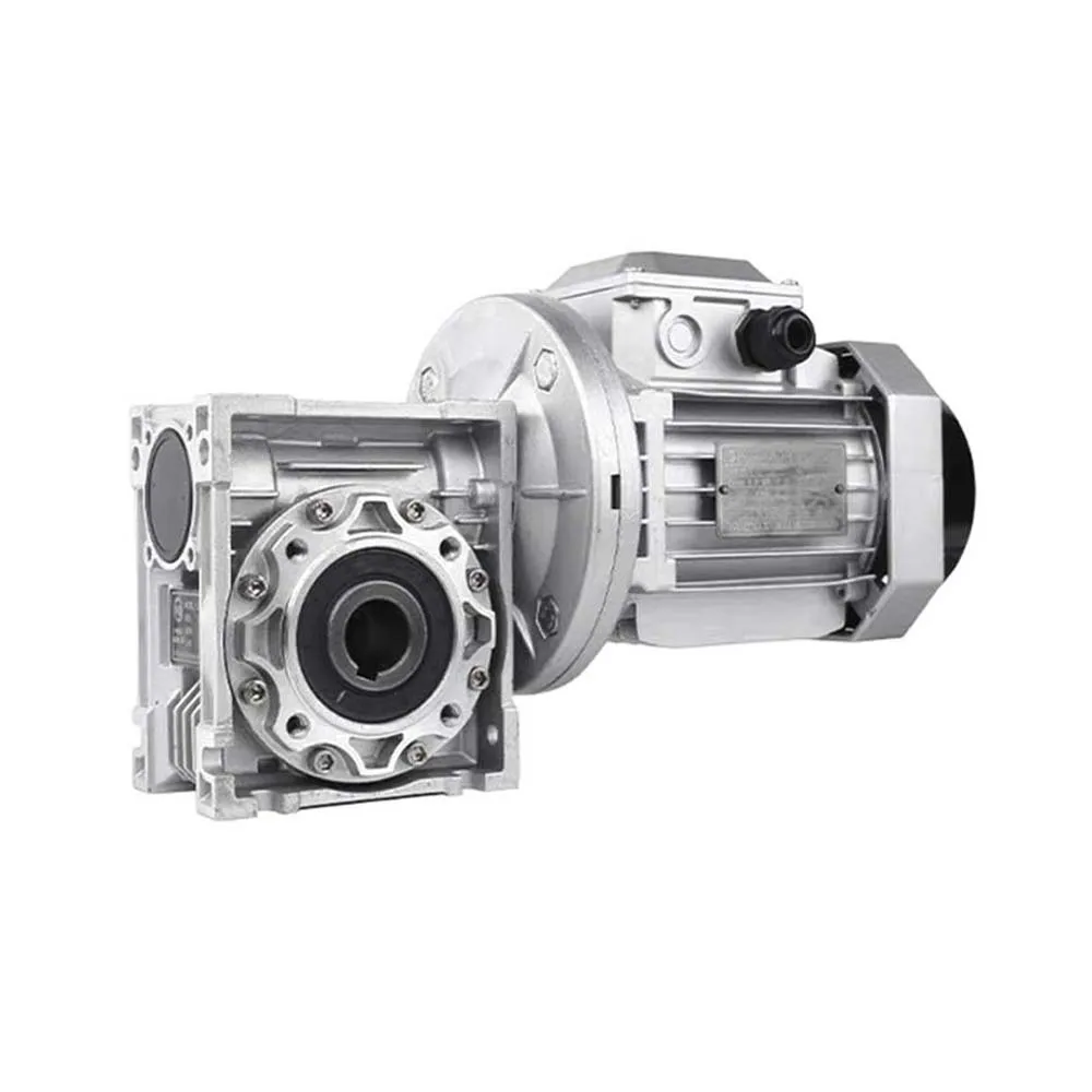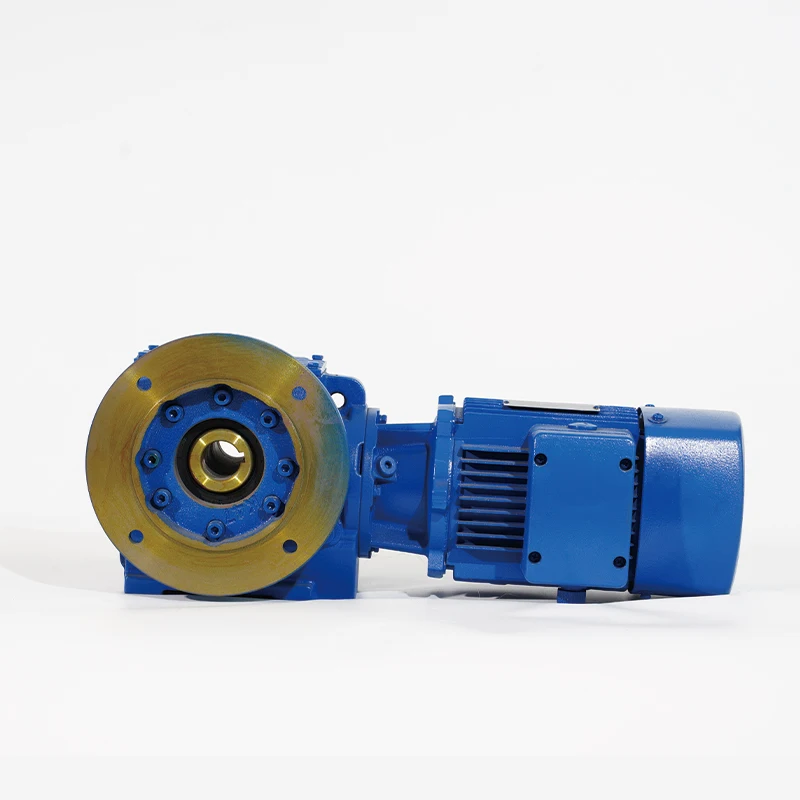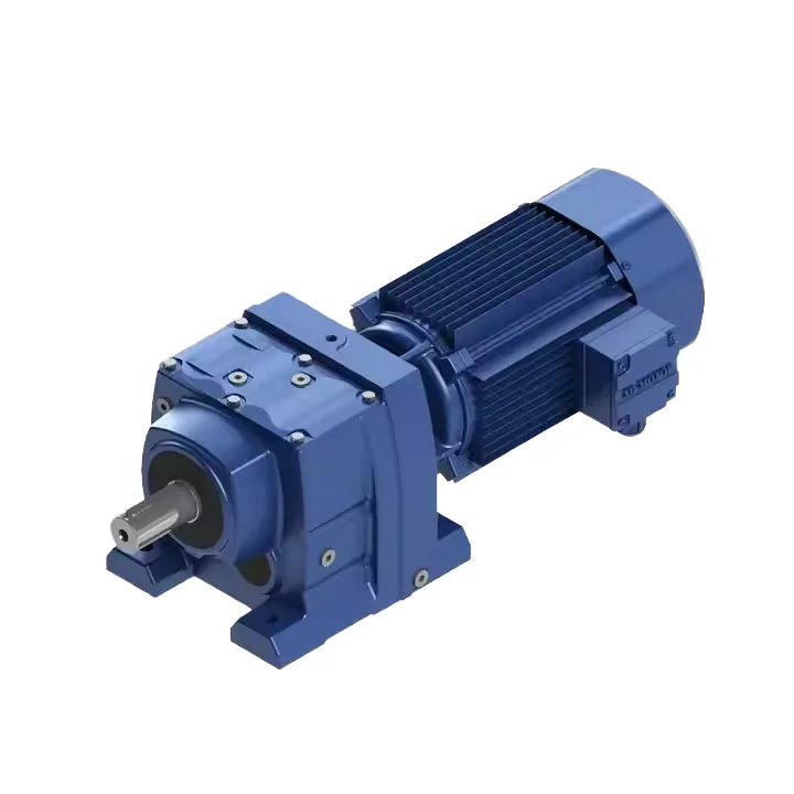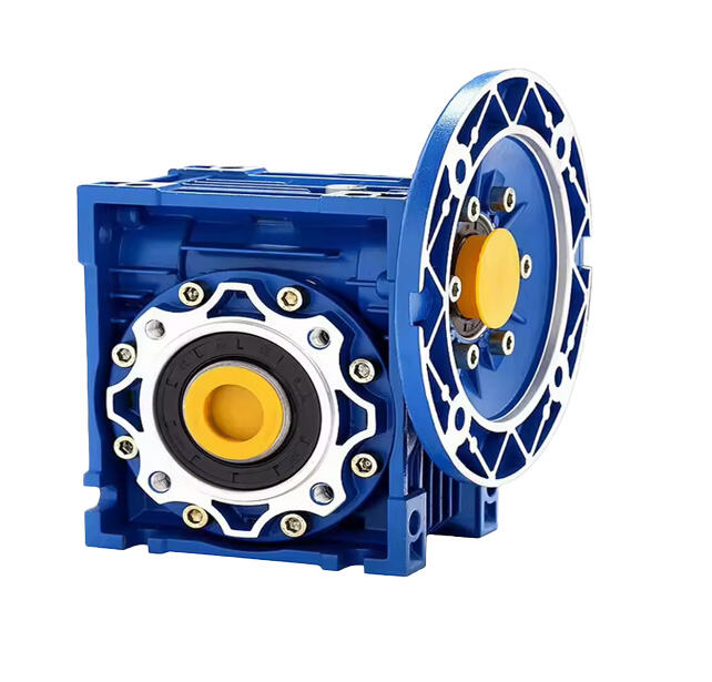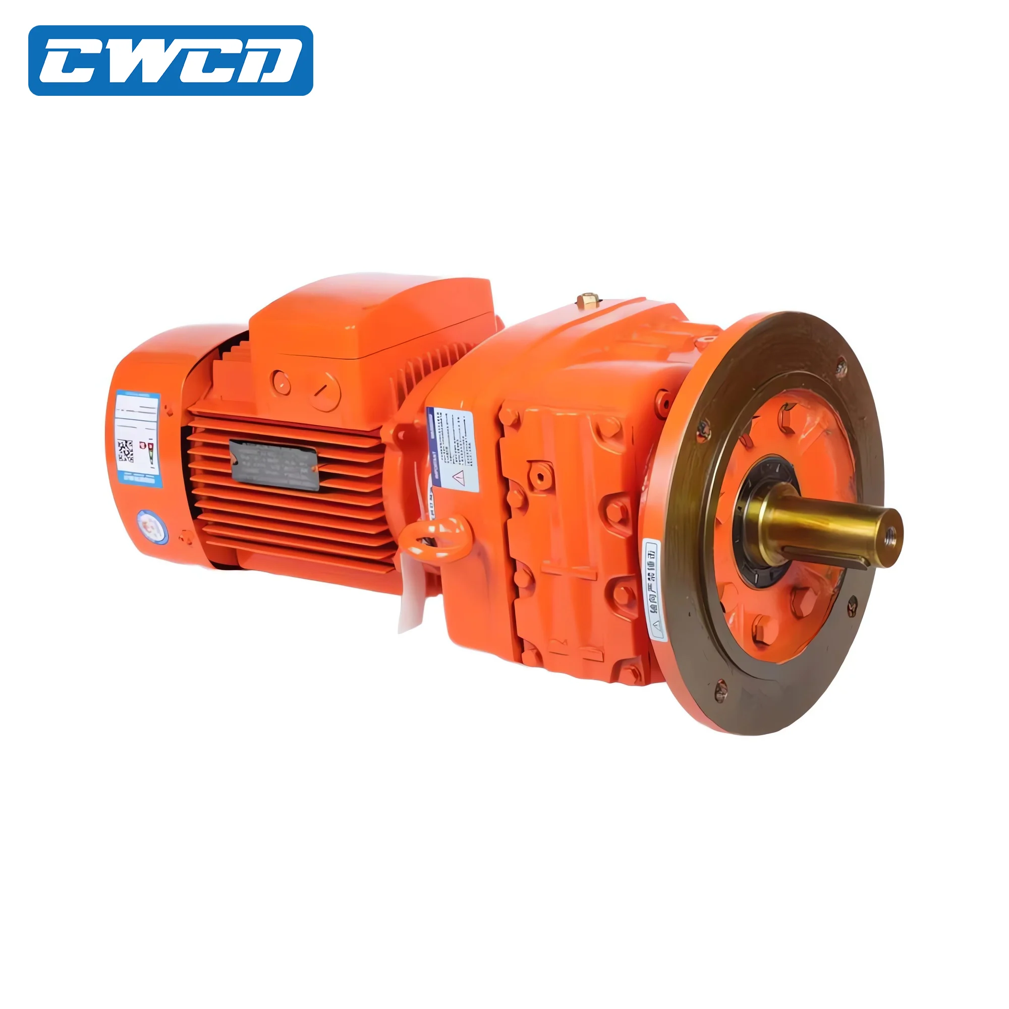
Different types of speed reducers work their magic on mechanical power in various ways, each designed for particular performance needs. Take worm gear reducers for instance they pack impressive single stage reduction ratios sometimes as high as 100 to 1 into small spaces. However these units tend to run at lower efficiency levels around 50 to 90 percent mainly because of how the teeth slide against each other during operation. Helical gears take a different approach with their angled teeth engaging progressively which results in much smoother and quieter operation compared to worm gears actually about 30 percent quieter in most cases. Plus they boast better efficiency ratings ranging from 92 to 98 percent. When space matters most planetary reducers shine by concentrating torque within limited areas through multiple planet gears rotating around a central sun gear. This design delivers outstanding torque density along with remarkable precision. Cycloidal drives stand out for handling heavy shock loads thanks to their unique eccentric motion combined with roller pin interactions that go well beyond what typical gearboxes can manage. And let's not forget bevel reducers which come into play when machinery requires right angle power transfer especially useful in tight spaces or complex mechanical arrangements where shafts need to meet at 90 degrees.
Choosing the right reducer depends largely on what the application needs functionally and environmentally. Planetary gears tend to be the go to choice for robotics work, aerospace components, and CNC machines because they pack so much performance into small packages. These systems need consistent results time after time with pinpoint accuracy. Cycloidal reducers find their home in tough environments like mines, material handling operations, and rock crushing equipment. They just handle the constant pounding better than most other types. For food processing plants and pharmaceutical facilities, stainless steel helical reducers make sense since they can withstand frequent cleaning without corroding and keep noise levels below 70 decibels during operation. Worm gear reducers still hold their own in conveyor belts and packaging lines despite being less efficient. The space saving design matters more there, plus the self locking feature provides an extra layer of safety when things stop moving unexpectedly.
Performance trade-offs across architectures directly influence lifecycle cost and system reliability:
| Reducer Type | Peak Efficiency | Noise Level | Shock Load Tolerance |
|---|---|---|---|
| Planetary | 95–98% | Low | Moderate |
| Helical | 92–98% | Very Low | Low |
| Worm Gear | 50–90% | Moderate–High | High |
| Cycloidal | 75–85% | Moderate | Very High |
The planetary and helical gear designs really boost efficiency because they use rolling contact between gears along with specially shaped teeth that work well together. These types are great for applications where the machine runs continuously without stopping much. On the other hand, worm gears and cycloidal drives focus more on being tough rather than super efficient. That makes these models better choices when dealing with stop-start operations, situations involving heavy shocks, or places where there might be unexpected overloads. Both cycloidal and planetary reducers can handle sudden torque increases that go way beyond their normal rating sometimes hitting around three times what they're supposed to manage. This capability matters a lot for machines with high inertia such as industrial crushers and mixing equipment which often require extra power at startup.
Precision matching of speed reducers to operational parameters prevents premature failure and ensures energy-efficient operation. Torque demand, input/output speed, and required gear ratio must be evaluated together–not in isolation–to preserve motor-reducer compatibility and long-term reliability.
The way loads are applied determines what kind of durability equipment needs to handle. When machines run at constant speeds, like conveyor belts moving materials around a factory floor, they create what we call continuous torque. But if this load stays too high for too long, components start to heat up and wear out faster than expected. Then there's starting torque, which is that big power boost needed to get heavy machinery moving from a standstill. Think about industrial crushers or plastic extruders where startup forces can hit anywhere between 1.5 to 2 times the normal operating level. That's where planetary gearboxes really shine because their design spreads out the workload across multiple points while packing a lot of strength into compact spaces. Another important consideration comes during acceleration periods when speeds change rapidly, such as in elevator systems or those self-driving warehouse robots everyone talks about now. These situations put repeated stress on gears that need special reinforcement against breakdowns. Failing to account for these different types of loading patterns often results in problems down the road including broken teeth on gears, damaged bearings, or even complete coupling failures particularly when initial power spikes go beyond what was originally planned for in the design specifications.
Gear ratio is defined as input speed divided by output speed and determines mechanical advantage. For example, reducing a 1750 RPM motor by 5:1 yields 350 RPM output while increasing torque fivefold–minus efficiency losses (e.g., ~95% for planetary, ~75% for worm). This inverse speed-torque relationship requires careful balancing:
When choosing equipment, it's essential to consider peak torque requirements, especially those sudden spikes during startup and acceleration phases. The rule of thumb is to include at least a 20% safety buffer in these calculations. Take a typical centrifugal pump as an example scenario. If it draws 50 Newton meters continuously but jumps to 90 Newton meters at startup, then we're looking at needing a reducer capable of handling around 108 Newton meters minimum. Getting this right matters because misalignment between components can create all sorts of problems down the line. Motor and reducer interfaces need careful attention too. When done properly, power transfers smoothly through the system. But get it wrong and watch out for those nasty side effects like unexpected vibrations or premature wear caused by off-center forces building up over time.
Extreme environmental conditions really take their toll on lubrication systems and how long machinery lasts. When temperatures climb past 140 degrees Fahrenheit (about 60 Celsius), regular mineral oils start breaking down fast. Synthetic options hold up much better though, keeping their thickness and protective qualities even when things get hot. Cold weather presents another challenge altogether. Standard greases tend to harden at freezing temperatures, which is why special low temp formulas exist to avoid problems like poor lubrication and equipment seizing during startup. Dust, tiny metal particles, and moisture floating around in the air all contribute to faster wear and tear. That's why facilities like foundries or places handling grains need those IP65 rated sealed enclosures. For equipment operating in harsh chemical settings, marine environments, or wastewater treatment plants, using corrosion resistant components isn't just smart it's necessary. Saltwater exposure alone can cut bearing lifespan by roughly 40% if there's no adequate protection against rust and degradation.
How often equipment runs and what kind of environment it faces determines how we build and maintain it. For systems running non-stop, say those conveyor belts working around the clock, we need tougher gears, bigger bearings, and special heat-resistant oils to keep things running reliably. These upgrades cut unexpected breakdowns down by about 30% compared to regular setups. When machines only run part time, we can save money on materials but still need good seals against water, cleaning chemicals, or dust getting inside. Double lip or labyrinth seals work well there. Equipment built with easy access points for greasing, replaceable seals that snap in quickly, and standard mounting holes lets maintenance happen much less frequently. We've seen maintenance intervals stretch over 200 extra hours in facilities where downtime costs real money. In food processing plants and pharmaceutical manufacturing, using FDA approved rubber seals and NSF H1 certified lubricants isn't just about safety standards it also makes inspections go smoother when regulators come knocking.
 Hot News
Copyright © 2025 by Changwei Transmission (Jiangsu) Co., Ltd — Privacy Policy